
Retrofitting USB port on older APC BackUPS with RJ50
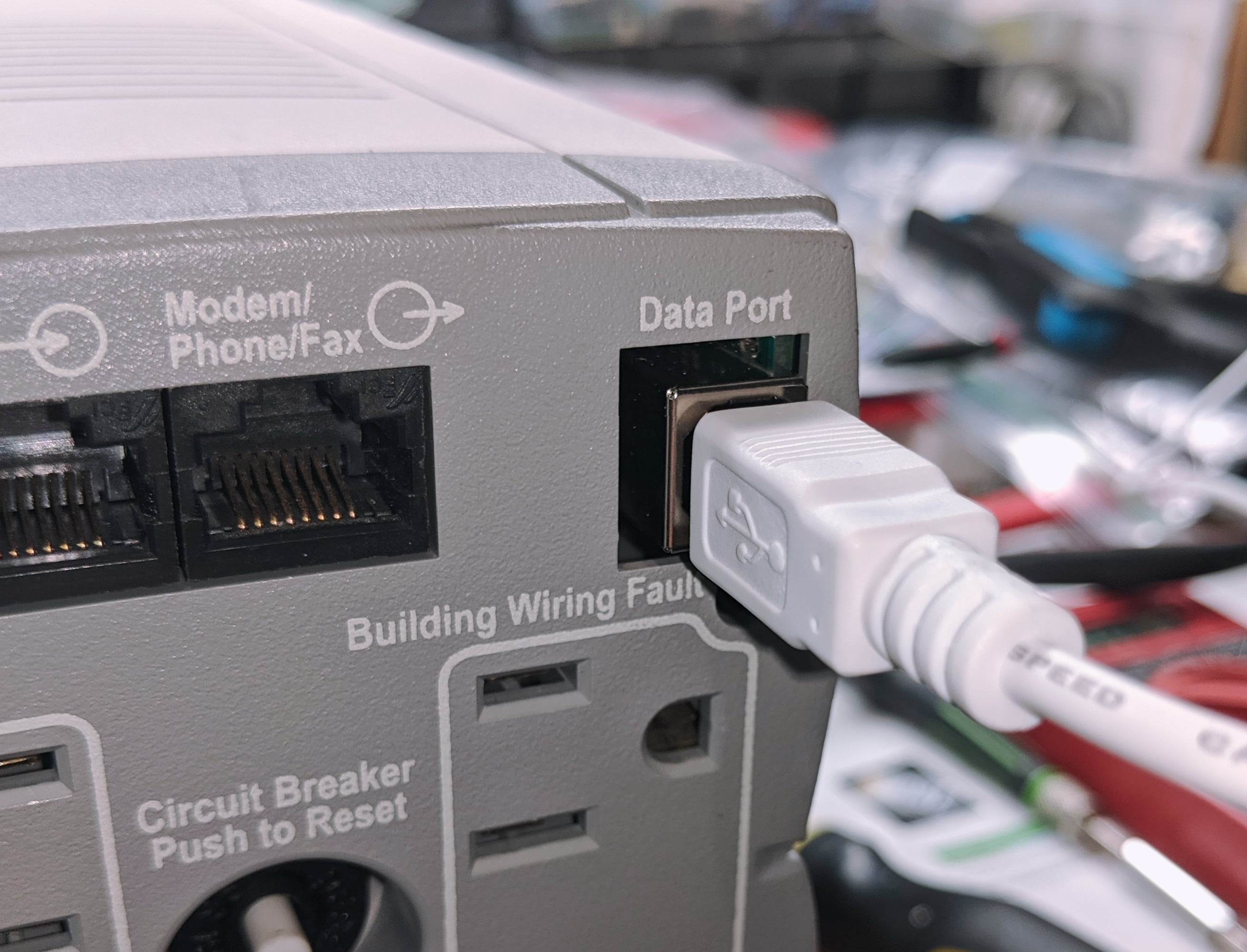
Before companies have standardized on USB, it was pretty common to find some strange connectors on equipment. Especially if they don’t want anyone to accidentally plug in the wrong thing. APC battery backups are a perfect example of using a RJ-50 plug to connect the USB signalling cable. To be fair, the RJ-50 plug with 10 contacts holds much more than just a 4-wire USB but in 2019, most people really just want the usb connection. You can find the adapter cable to do this but you will spend between $15-30 for that cable. Lets take a look at how hard it is to remove the RJ-50 plug and install a USB Type A connector.

Please be careful when opening 120VAC electronics. Keep your work space clean so you don’t have stray conductive materials touching the circuit board and don’t accidentally leave it connected to the outlet while working on it. When soldering, make sure you aren’t making new connections with sloppy solder joints or cold joints that have higher resistance and will heat up. Unlike normal 120VAC projects, if something is wrong, your circuit breaker will trip, a UPS will switch over and start producing its own 120VAC from its battery. While batteries have lower voltage and limited run time, they can produce FAR more amperage than your 15A breaker will allow. And as always, this will VOID YOUR WARRANTY.
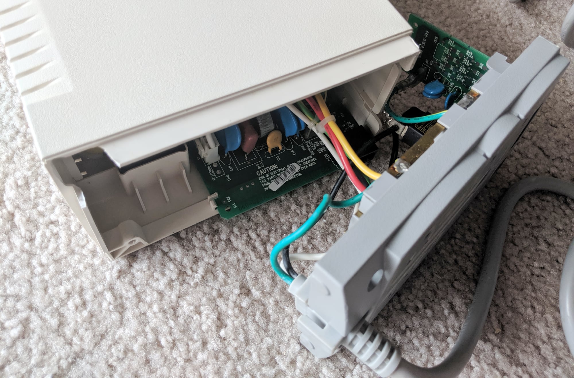
Step 1: Disassemble
APC did a great job building the plastic enclosure for this product to isolate and interlock components to reduce the risk of damage. Unfortunately for first time taking one apart, you will likely break some of the plastic joints.
- Remove the battery pack
- On the rear outlet panel, remove the 2 lower screws
- Remove rear outlet panel by pulling up from the bottom, rotating it 45 degrees out
- The white housing is 2 parts that slide apart, turn the unit on its right side (side with the RJ-50 data port), there is a large transformer that sits between the two pieces, let it rest on the right half
- Remove the battery leads
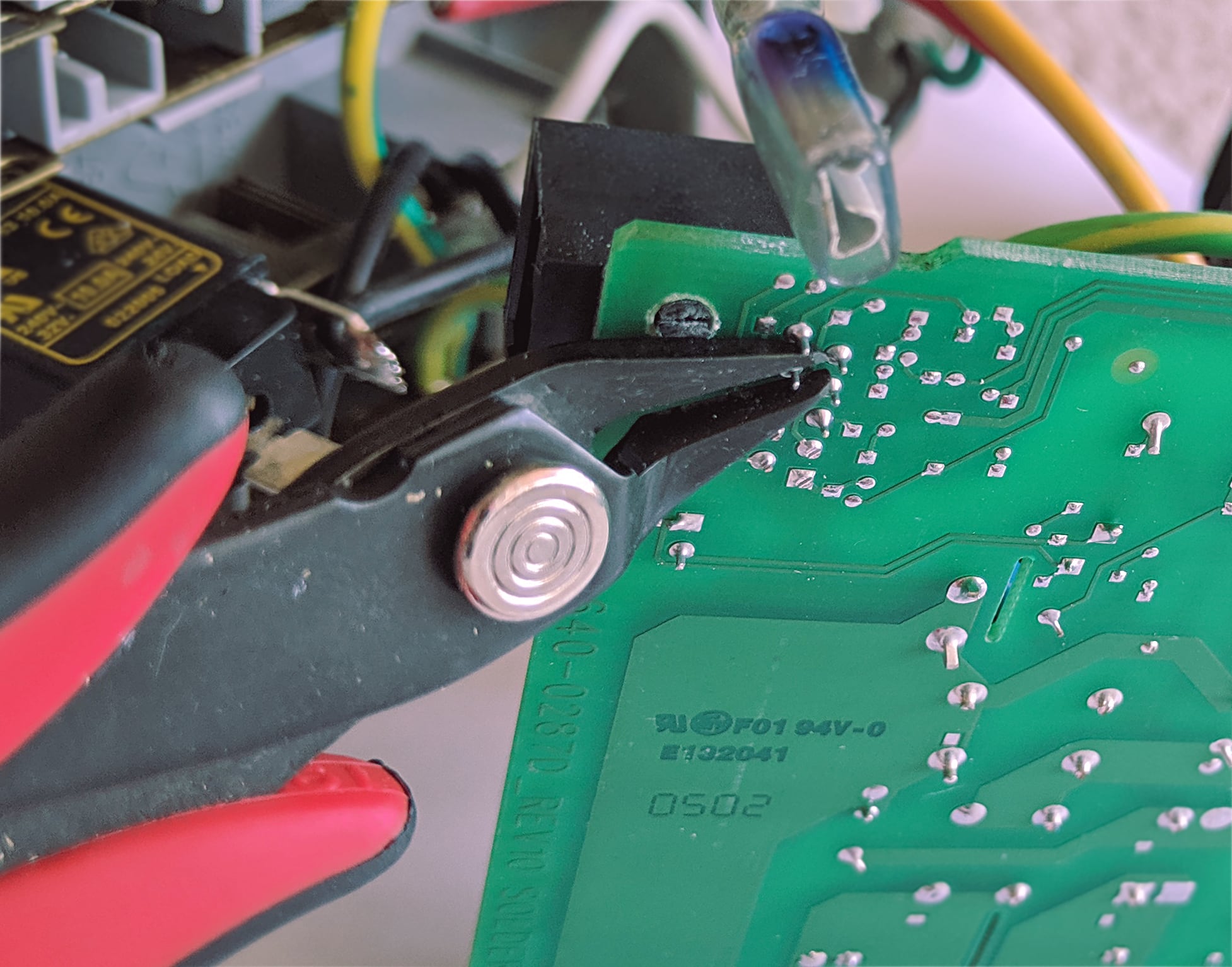
Step 2: Remove the RJ-50 Connector
We want to remove the RJ-50 connector and replace it with a USB socket so you don’t need that special adapter cable.
Removing components from professionally produced board can be tricky but here are some tips.
- Cut any plastic tabs holding the part to the circuit board – you can try to salvage the part to reuse it but its so much harder
- Cut any pins protruding from the solder as close as you possibly can – this will reduce how much wiggling you have to do
- Using a screwdriver or other flat object, apply tension pulling the part up, off the circuit board while you heat each solder joint
- Anything metal is going to get hot during this process, watch your fingers
- With 10 pins, it will take a few passes of heating up pin 1-2-3-4-5-6-7-8-9-10, with each pass you are getting 1mm of upwards movement
Step 3: Jumper the USB port
Since we are retrofitting a part that the circuit board is not designed for, we are not going to be able to line up the pins without jumpering the new part. This will let us wire the 4 pins of the USB port to any of the 10 pins of the RJ-50 port without having to worry about shorting any connections.
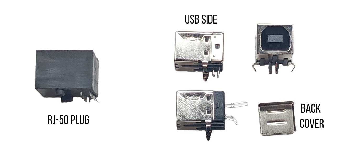
I ordered a 10 pack of USB Female Type-B 4-Pin Right Angle PCB Jack Socket for $4.
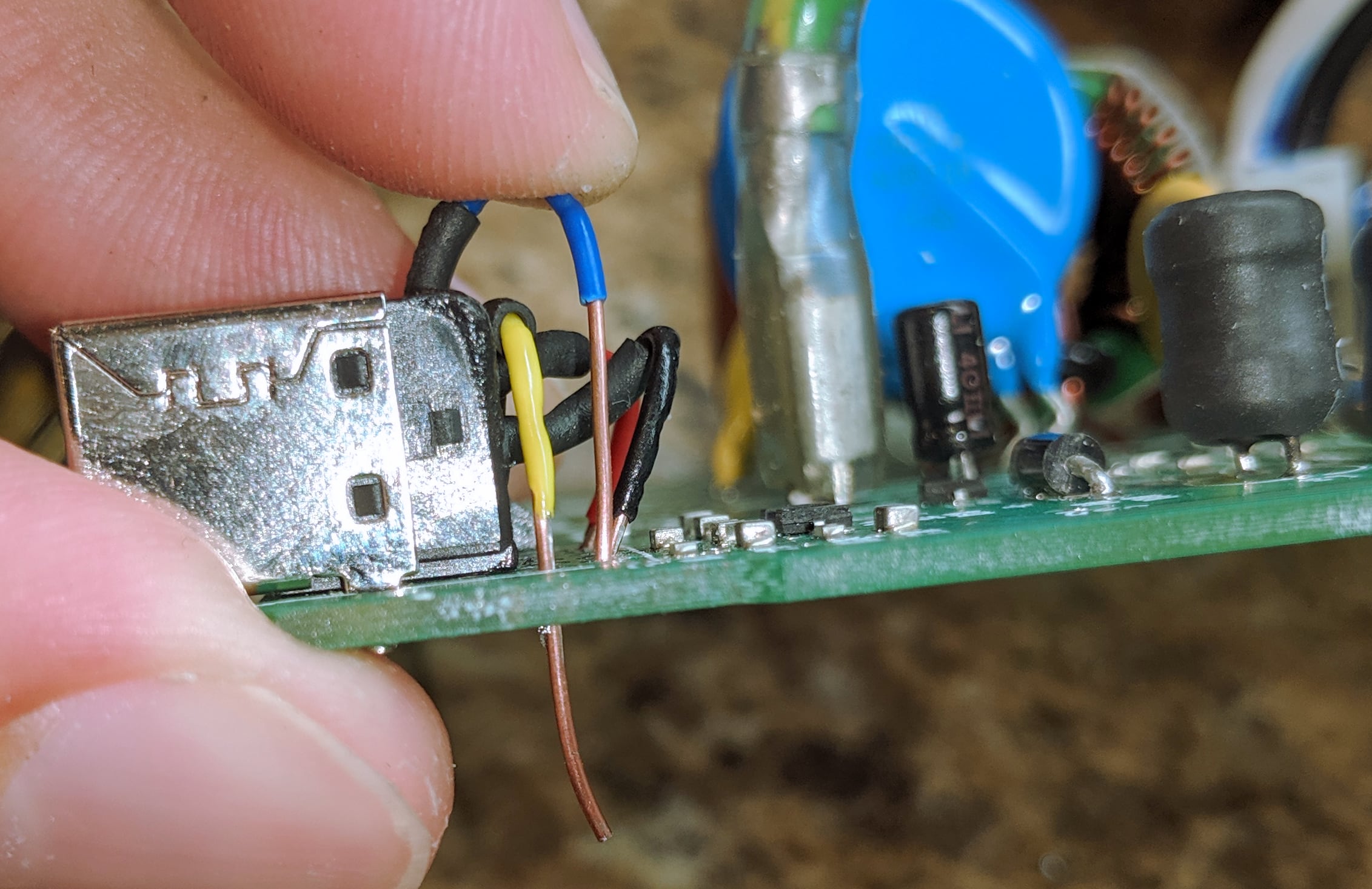
Using needle nose pliers or pick, peel off the back shield housing of the USB port to allow us to redirect the pins out the back of the part instead of down into the circuit board. Then cut some wires and solder them to the legs. I used heat shrink after solder each of these wires to cover up the legs and solder joint to stop any potential shorting between them.
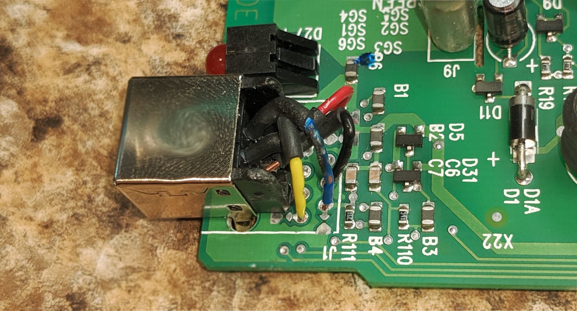
Next, we are going to place the USB port on the circuit board and bending the large mounting tabs so the USB port is securely attached to the board. If the legs are extending toward other components on the circuit board, use wire cutters to trim them back. You can also use hot glue or super glue to firmly attach this to the board if you plan to connect and disconnect USB alot.
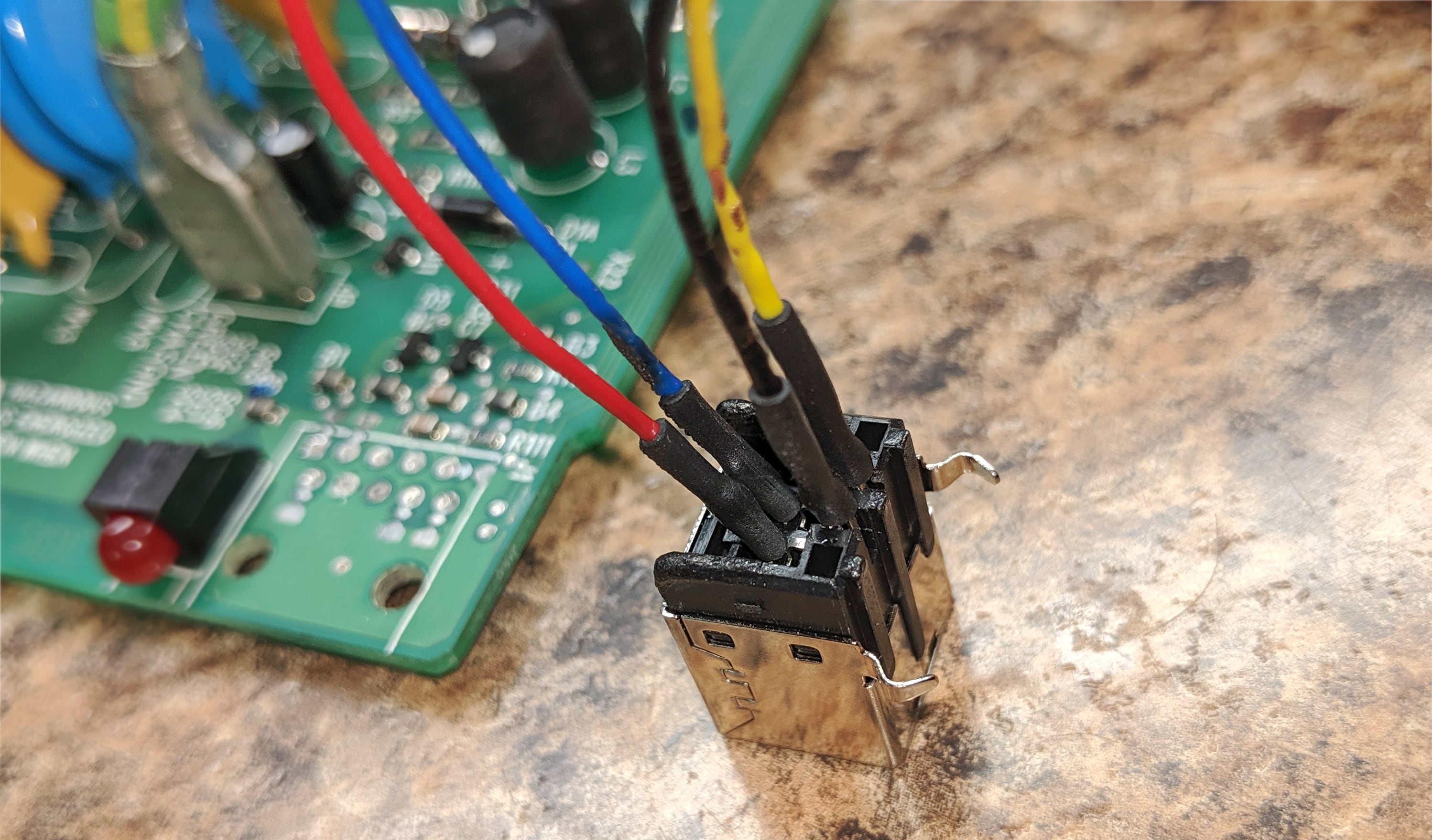
Step 4: Solder the USB Port
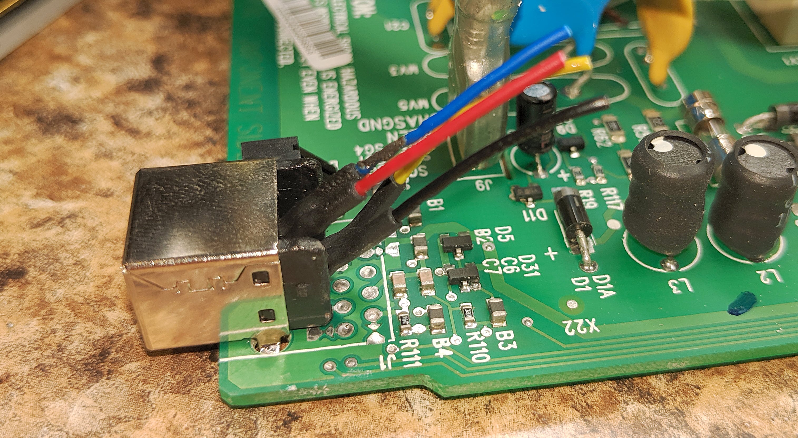
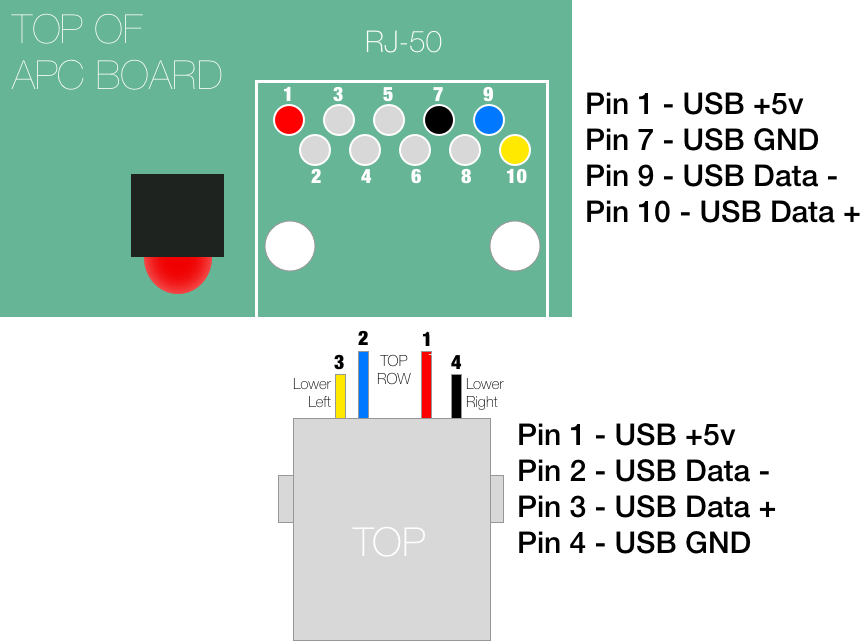
Next we need to attach the USB pins the correct pins on the APC unit. Since we are only interested in the USB lines, we only need to connect pins 1, 7, 9, and 10. As you can see, the jumper wires are truly the only way to get pin 1 of usb to pin 1 of the RJ-50 connector.
Strip the wires with large amount of exposed copper and we will trim the excess after they are through. You can cut them short in the beginning but you will have a much harder time maneuvering the wires to the correct place.
Since we remove the RJ50 port from the board, there will be leftover solder in the holes making it more challenging to get the new wires in. By placing the soldering iron on the underside of the board, you can heat up the solder and simply push the new wire through. Then add some new solder to the joint and trim the excess wire off. Do this with all 4 wires. Double check that no shorts are occurring between any of the lines especially if you have exposed legs from the USB port. If you don’t want to use heatshrink you can apply some hot glue to keep them separate but don’t over do it.
Step 5 : Reassemble
If you want to test it un-assembled, you will need to attach the battery or it stays in a flashing orange state with the open battery line.
Personally, if the junctions look good, I assembled mine and then tested it. Once you have taken this unit apart once, it is much easier to get it back apart if something is wrong.
The USB port is slightly smaller than the RJ-50 port which lets it wiggle around more. If you plan to connect and disconnect USB cables you might want to look at filling this gap to relieve strain on the circuit board.
You can test the voltages across the two outside pins in the USB cable for the 5V but I took a risk and just connected it to an older PC and it immediately identified it as APC device.
Conclusion
In the end, I have a USB APC unit.
Was it worth the amount of time to do this? Probably not. Those RJ-50 to USB cables are just pricey enough that its on the edge of willingness to buy one vs the simplicity of just having an USB port on this unit. I’m glad to see APC newer units just have USB on it. I went down this road because I run across so many older APC units without the cable. I bought this APC Backup CS 500 from refurbups.com for $50 shipped and could of bought the cable for another $15. Couple hours and $4 for a 10 pack of usb sockets, and here I am.
If you have questions, let me know.
Why retrofitting APC Back-UPS CS might be worth it
You can buy a lot of cheap battery backups with USB support but the Back-UPS CS line are much more versatile and configurable. Most others have hard coded values when they will switch to battery and this model lets you set the voltage thresholds and sensitive. Also, I always disable the alarms on these. If you are not fully loading the battery backup to where it has almost no run time, the beeping from these units gets old fast. I wish it could just chime once when switching between line and battery power but it doesn’t have that option.
If you are connecting this unit to a Linux box, there is a great command line tool called apcupsd which has this config tool apctest.
sudo service apcupsd stop
apctest
It can set these parameters: (I’m sure windows has a nice tool to do this too)
1) Test kill UPS power
2) Perform self-test
3) Read last self-test result
4) View/Change battery date
5) View manufacturing date
6) View/Change alarm behavior
7) View/Change sensitivity
8) View/Change low transfer voltage
9) View/Change high transfer voltage
10) Perform battery calibration
11) Test alarm
12) View/Change self-test interval
Q) Quit

Current alarm setting: ENABLED
Press…
E to Enable alarms
D to Disable alarms
Q to Quit with no changes

Current LOW transfer voltage setting: 92 Volts
Enter new LOW transfer voltage (0 to cancel): 0

Current HIGH transfer voltage setting: 139 Volts
Enter new HIGH transfer voltage (0 to cancel): 0

Current sensitivity setting: LOW
Press…
L for Low sensitivity
M for Medium sensitivity
H for High sensitivity
Q to Quit with no changes
APCUPSD shows COMMLOST
On linux, the default config has a serial device line. Comment the Device line with a # and run sudo service apcupsd restart.
sudo vi /etc/apcupsd/apcups.conf
# or
sudo nano /etc/apcupsd/apcups.conf


UPSTYPE usb
#DEVICE /dev/ttyS0
Dell RPS-720 Cable Pinout
UTC Conversion to United States Timezones

I'm a 36 year old UIUC Computer Engineer building easy to use tech to simplify our complicated lives with an interest in golang, rust, 3D printing, ESP32 and Arduinos.
THANK YOU. What a brilliant idea. I was going to try to jury rig an old USB cable and network cable. This is much better. Thanks for taking time to post this. Now I have another project!!!!
Thanks for the information! I didn’t have any spare usb sockets handy, so I used a spare usb cable and cut off one end. It took a bit of effort to map the colors of the usb cable wires to be able to solder the wires to the appropriate pins on the pc board. The APC BE 450G has a slightly different pc board appearance, than the unit picture above. Pin 1 on the reverse side of the RJ-50 socket has square pc board trace, as it typical of the convention, usb +5 vdc.
It now works with NUT just fine, after a bit of reconfiguration of usb.conf.
Excellent, thank you for this, much appreciated! Those replacement RJ-50 cables are dang expensive.
Instructions and drawings were so clear I soldered usb cable directly to PCB, put it back together w/o testing and it works! Thank you.
Thank you, really helped me out. I found a couple 2004 APC CS 650 at the recycling station and got some new batteries for them.
Always wanted a UPS to protect my micro server running Proxmox and some apps for home automatization.
next step is to set up Proxmox to shut down the server on power outage.
Great work
Great write up! Thank you very much! Saved me from buying a cable or figuring out Pinout myself. Got connectors on sale for only 0.14AUD from local electronics shop. They are also on AliExpress for 3AUD for 10x